Learn more information about our products. Our FAQs are here to help answer your questions and queries about our product range. If our FAQs however don’t answer a question you have please feel free to give us a call on 4966 5211.
FAQs
Radios
No. There is an embargo from the ACMA on NEW LICENSES being granted for 900 MHz, but the unlicensed ISM band (915-928MHz) is still available and free to use for various Industrial, Scientific and Research applications. There are hundreds of thousands of ISM band devices deployed in Australia they are a great alternative to licensed products for many organisations.
Frequency Hopping Spread Spectrum transmission is the repeated switching of frequencies during radio transmission to both deal with interference and avoid interception. Under a FHSS system, the transmitter hops according to a pre-configured pseudo-random pattern and the receiver needs to be on the same pre-configured pseudo-random pattern to be able to “de-spread” the signal and put it back together correctly. A short burst of data is transmitted on the current narrowband channel, and both the transmitter and receiver tune to the next available frequency in the pre-configured pattern. Because of the speed of the hops (many times per second) no channel is being occupied for long, and the chances of another transmitter being on the same channel at the same time are very low. In Australia, 900MHz FHSS systems utilise 66 channels across free the 915-928MHz ISM (Industrial, Science and Medical) band.
DSSS is a related technique to FHSS. It also spreads a signal across a wide channel, but it does so all at once instead of in discrete bursts separated by hops. The advantage of DSSS is that it can achieve higher throughputs than FHSS, but DSSS is more susceptible to interference than FHSS and so care needs to be taken in designing and deploying a DSSS network unless it is in an RF isolated location with no other 900MHz traffic around.
It depends on which type of unlicensed radio you are using. WiFi is unlicensed and yes in some ways some WiFi networks are vulnerable to cyberattack, but 900MHz Frequency Hopping Spread Spectrum technology is inherently secure and is notoriously difficult to intercept and jam. (Which is why it has been a favoured technology in Defense applications for decades.) So if you are deploying a 900 MHz FHSS unlicensed solution not only are you saving on license fees, you are also getting an inherently secure connection for your proprietary data.
The major things you should be looking for are:
- Range
- Reliability
- Operating Temperature
- Receiver sensitivity
- Support
- Ease of Configuration/operation
- Data throughput
- Power consumption
- Number of Hopping Channels utilised
- Compliance with local regulations
- Support
- 900MHz FHSS transmitters in Australia can only access the 915-928MHz band. (66 channels.)
- The number of channels available may limit throughput in some applications – talk to Control Synergy to assess what throughput you will be able to achieve legally. Different 900MHz vendors achieve different throughput figures, and we can help tailor your hardware to your data requirements.
- Transmit power is limited in Australia to 1W EIRP (Equivalent Isotropically Radiated Power) at the Antenna, which limits the distances that data can be sent. Other parts of the world are able to transmit at 4W EIRP, with a correspondingly large increase in transmit range.
As a National Importer and Distributor of 900MHz radios Control Synergy takes responsibility for the radios we sell to be compliant with local ACMA regulations. We certify every radio we sell and make sure that it is configured to comply with ACMA requirements.
Many overseas areas allocate a broader set of channels to the ISM band than Australia does. For example in the United States, users of 900 MHz radios are allowed to hop from 902-928 MHz. If you try to operate one of these radios in Australia, you will be encroaching on parts of the Spectrum owned and paid for by Australian Telcos and you may be exposed legally if discovered. Don’t know if your radios are compliant? Give us a call and we will help you find out
Receiver sensitivity is a measurement of how sensitive the ears of your radio network are. Receiver sensitivity varies greatly from vendor to vendor and is a function of good RF design on the radio board and the quality of components used in the construction. A good figure to use as a reference is -110 dBm which is a measurement which indicates the ability to hear down to a very low level.
Control Synergy has deployed 900 MHz Networks sending and receiving data over distances of up to 32km. That was achieved with radio equipment with receiver sensitivity of -110 dBm.
Powertec
There are a couple of options here:
- The Cheapest Install a large 4G Antenna on the roof of your VAN/Motorhome then run coax down from the Antenna into your 4G/WiFi router. Your Router will now have a much larger set of eyes and ears to ‘see’ and ‘hear’ the nearest TELCO Tower. If you set up an Omni Antenna you won’t have to align the Antenna to the Tower, but the downside is that you won’t be able to ‘see’ and ‘hear’ as far. If you set up a Directional Antenna on the top of your Caravan, you will be able to ‘see’ and ‘hear’ further, but you will need to make sure that each time you set up camp you have the Antenna aligned to the nearest TELCO tower.
- Best Install a Australian Certified 4G Amplifier in your Van instead of the traditional 4G/WiFi router. Plug the 4G Antenna on your roof into the Amplifier and then enjoy the signal. The Certified Amplifiers from Control Synergy will boost any signal they find by a factor of at least 30. (As long as there is some level of signal to start with.)
The mobile Phone Amplifiers sold by Control Synergy are all certified by Australian Telcos to operate on their Networks. You will absolutely be complying with Australian Telco rules if you use and install a Control Synergy Mobile Phone Amplifier correctly.
Yes. The mobile phone Amplifiers will boost 4G signal and then if for some reason the 4G signal is unavailable, the Amplifier will fall back to boosting 3G.
As long as there is some level of signal to work with initially, you should see your voice and data signal increase by at least a factor of 20.
Yes. The Control Synergy Mobile Phone Amplifier comes in a Fixed or Mobile version. The Mobile version is designed to be installed in your vehicle and look for the nearest 4G Tower as you are driving. As it picks up a 4G tower it boosts the signal back inside the vehicle allowing you to maximise your voice and data rates. The Control Synergy Mobile Phone Amplifier Vehicle Kit will manage the Handover from Tower to Tower leaving you free to concentrate on the road.
Yes. TELSTRA, OPTUS and VODAFONE are all covered. You need to be aware that different TELCOs own different slices of the 4G spectrum, so performance across different TELCOs may be different.
No. Control Synergy is a specialty distributor and we don’t do installation work. We have a number of partner companies across Australia who can assist with installation, please let us know which area you are in and we will organise one of our contacts to get in touch.
MBConnectline
The big advantage that 4G has over other forms of Wireless Communication (eg WiFi) is that 4G data is encrypted to recognised international standards. This is why large corporations are (eg Banks) are happy for customers to conduct Financial Transactions over 4G connections. The cyber security threat with Remote access is not so much the Public 4G Network as the point of interaction with that 4G network. (ie the App). Apps are written in code and the standard expectation around flaws is that for every 1000 lines of code there will be between 15-50 flaws. At a minimum you could expect 1 error every 67 lines of code. And it is these errors that hackers attempt to exploit. To protect your remote Access connection, you would be well advised to add an extra layer of protection to the standard 4G encryption.
Request a Fixed/Static IP Address from your Telco for your Remote Access
Usually when you connect to a Network, the Network Administrator assigns your device an IP address which changes each time you make a connection. This can be tricky if you are wanting to use the Network to make a remote connection to your end device, because your end device will not know which IP address is authorised to connect to it. One way around this is to have the Network assign a FIXED/STATIC IP address for your connecting device. This means that you can tell your end device exactly which IP address or addresses is allowed to connect to it. It also means that any potential hackers are going to need to know your STATIC IP address if they are wanting to make their own connection. Not all plans and not all Telcos offer fixed IP addresses on all plans, so check with your Network Provider. There is usually an additional charge for FIXED IP services.
Use a Router that operates on a secure protocol such as OpenVPN
A router is designed to connect two networks together. Cheaper 4G routers tend to use lower levels of communications and security protocols, whereas a 4G Router that is designed from the ground up with cybersecurity in mind is built around a secure communications protocol such as OpenVPN. OpenVPN constructs a secure communications channel between a VPN Client and the VPN server. A 4G router communicating with factory installed OpenVPN is ready to go straight out of the box and so there is no need to arrange a FIXED IP address.
What are some other advantages of using OpenVPN for secure remote access?
- OpenVPN uses 256 bit encryption keys and high-end ciphers which provides good protection against ‘Man-in-the-middle’ attacks. A ‘man-in-the-middle’ attack is where an unauthorised person or device attempts to fool the network into thinking that it is a legitimate user and can access data intended for somebody else.
- OpenVPN run on almost all platforms, so it doesn’t matter if you are a Windows or a Linux user. Platforms that support OpenVPN include MacOS, Android, iOS, FreeBSD and many more.
- Good compatibility with Firewalls OpenVPN can use any port on TCP or UDP, which means it is easy to deploy OpenVPN where the internet is involved. Even when firewall based blocks are in place around a particular port, OpenVPN connections usually make it through. For example, if OpenVPN uses TCP with port 443, then the connection will appear as a typical HTTPS connection and will be allowed to pass through the firewall.
- Cost benefits OpenVPN is free software and can be downloaded for use in Windows, Linu, MacOS, iOS and Android devices. OpenVPN Client allows free connections to an OpenVPN server. When used in a Server configuration, OpenVPN provides free connections from up to 2 Clients.
Because Open VPN is designed around a VPN Client and a VPN Server, there can be quite a bit of configuration involved in getting your application working. If you are a software person by training, you will have no problems, but for the rest of us it is generally going to be best to use a product that already has OpenVPN built-in. This means that all the VPN Client and VPN Server communications are already set up and are taking place in the background once you take the 4G router out of the box and start to fire it up.
MBConnect24 is the Remote Services Portal operated by MBConnectline, a German Cybersecurity company who also manufacture hardware designed to connect to the Portal. The MBConnect24 portal is hosted on an OpenVPN Server in an Australian High Performance Secure Data centre which is monitored 365 days per year, 24 hours per day. The pre-configured platform is set up within minutes via a web browser and requires no special IT knowledge or network expertise. The MBConnect24 portal allows secure central management of multiple customer devices across multiple sites, all via an OpenVPN server to OpenVPN client connection.
No. The Remote Access Portal is supplied free with MBConnect Remote Access hardware.
Yes. Please contact Control Synergy to discuss.
MBDialup is the VPN Client software developed by MBConnectline to connect to the MBConnect24 Remote Services Portal to allow for secure remote access to your end devices. There is no need to install and multiple programs to facilitate Secure Remote Access, just initialise MB Dialup and you have a secure VPN connection to the Remote Services Portal.
- Windows 7 32/64 Bit
- Windows Vista 32/64 Bit
- Windows 8 64 Bit
- Windows 10
The mbNETmini is the quickest and easiest way to enjoy the benefits of Secure Remote Access. It is a compact Industrial Router with a built-in DIN Rail Mount which makes it easy to install into commercial deployments. The mbNETmini offers secure access to Ethernet Devices and Networks through the MBConnect24 Remote Services Portal.
The mbNETFIX is an Industrial Firewall in a Compact Din Rail mount form factor. It is aimed primarily at controlling and directing traffic around Automation and Control Networks. It can be used as a NAT Gateway to provide access to legacy segments of the OT or production Network. It is not primarily a Remote Access product but because of the NAT capabilities it does make connecting to different segments of the OT Network easier and more secure. The mbNETFIX is also a quick and easy way to raise the overall level of cybersecurity around older Machines running legacy OS like Windows 7 and Windows XP.
Laird Connectivity
Laird Connectivity are one of the worlds’ largest Antenna Designer and manufacturers with multiple production facilities across the USA and Asia.
Antenna Gain is the ratio of power transmitted in a certain direction with a specific reference point. Antenna efficiency is how much of the RF power that is delivered to the antenna (from the radio) is actually transmitted into the air. Mathematically, the relation between gain and efficiency is G = E x D where D is the directivity and E is the efficiency.
Not always. It depends on what you are trying to achieve with your antenna. Too much Gain in a directional antenna might overpower the radio system and so lead to component failure. Too much Gain in a mobile antenna flattens out the propagation pattern and may mean that in Hilly or obstructed terrain you will lose connectivity. Talk to Control Synergy about what you are trying to do and we will help you source the right antenna for your system.
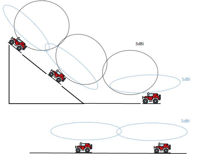
‘dB’ is a convenient way of measuring electromagnetic power. It is a logarithmic scale which essentially shows power doubling every 3dB. ‘dBi’ measures power against a theoretically ‘perfect’ isotropic radiator (ie an antenna that emits power constantly in all directions.) ‘dBd’ measures power against a reference dipole antenna. So they are both ways of measuring power output of an antenna, but because dBi is measuring against a ‘perfect’ radiator, the dBi figure is usually seen as more reliable. To work out the Highest gain antenna, take the dBd figure and add 2.15 dB to reach the dBi figure. In other words, a 7dBi antenna has slightly higher gain than a 5dBd Antenna.
Omni’ is short for ‘omnidirectional’ so an omni antenna sends out signal in all directions and is capable of receiving signal in all directions also. For mobile applications you will pretty much always need an omni antenna. Omni antennas vary in performance characteristics depending on the frequency and distances you need to send and receive data.
A ‘Yagi’ is a type of Directional Antenna, named after one of the Engineers who developed it in the 1920s, Mr Hidetsu Yagi. The advantage of the Yagi design is that for a given physical size, the power output is maximized, so where space constraints exist, then typically a Yagi will give the best performance. However, if there are no special space constraints, you may well be able to find another kind of Directional Antenna that will provide higher output.
Some antennas come with standard lengths of coax and standard connectors, but Control Synergy also offers a Custom Coax and connector service. Contact Control Synergy to discuss what is the right type and length of coax for your antenna system, as well as what is the appropriate connector.
Laird Connectivity is committed to the long-term supply of all its standard embedded wireless modules and packaged products. Laird Connectivity’s products are specifically designed to meet the needs of the industrial and medical markets, which typically require 7 – 10 years product lifecycle. Although Laird Connectivity can’t guarantee that a component used in our products will not be obsoleted and cannot be reasonably substituted, Laird Connectivity can assure customers we will continue to sell our product when we have customer demand and can obtain the necessary components to build our products.
MIMO refers to multiple-input, multiple-output technology and is used with 4G antennas to maximise performance of the MIMO radio. A MIMO antenna setup includes two or more antennas located or associated with a single physical structure. Each antenna element is used to simultaneously transmit and receive signal streams, providing better coverage and greater capacity.
‘LoRa’ stands for ‘Long Range’ communications and is a communications protocol used frequently in iOT communications. It uses a form of spread spectrum technology over the ISM (Industrial, Science and Medical) band. In Australia the ISM band is 915-928MHz.
Yes. Control Synergy only sells the Australian certified version of the LAIRD Sentrius gateway in Australia. If you think you might have purchased a non-certified Gateway inadvertently, please contact Control Synergy to discuss.
No. The US LoRa band is 902-928 MHz and if you use these devices in Australia you may be interfering with other commercial users on the 900 MHz band such as Telcos. Talk to Control Synergy to see whether the device you are using is Australian Certified.
No, the LoRa device will broadcast and its’ data may be received by more than one gateway. The gateway configuration then determines what happens next to the received data. Typically, it will be passed to a network server that will process duplicate packets received by multiple gateways.
LoRa is the physical layer or modulation technique used for long-range, low-power communications links. LoRaWAN is a communication protocol and network architecture that sits on top of the LoRa physical layer. It is possible for a radio to use LoRa but not use LoRaWAN. Laird’s Sentrius Gateway modules use a LoRa radio and the LoRaWAN protocol.
A private LoRaWAN network is usually made up of a single application with network infrastructure provided by a single organization. A public LoRaWAN network will support multiple applications from multiple organizations. But the lines between private and public can be blurred. When considering LoRAWAN you need to consider: Do you want to subscribe to an established LoRaWAN network operator and possibly pay a subscription? You provide the end devices. Do you want to join a community LoRaWAN network where gateway access is available to all users (applications) in the network for the good of the network? Do you want to have complete control of the network and become an operator yourself? You can restrict application access just to your own applications or open it up to others. Anyone can set up a LoRaWAN network and become an operator; this is particularly useful if you need to cover a small area such as a single factory or campus. Obviously covering a larger geographic area becomes more difficult and therefore you might be better served by subscribing to an established operator with more widespread coverage. As an alternative, you may want to join a community network and allow others to benefit from your local coverage while you benefit from the coverage provided by others elsewhere. The Laird Sentrius Gateway supports all of the above scenarios. Contact Control Synergy about your LoRaWAN application to find the best solution for you and your customers.
No. The Sentrius gateway implements LoRaWAN which defines the communication between end nodes and a gateway up to the network/cloud. LoRaWAN does not define any communication between end nodes; all communication from end nodes goes directly to the gateway. A proprietary protocol would be required to communicate between end nodes which we have not implemented at this time.
The NMO mount was developed by Motorola to facilitate quick and easy mobile antenna installation. It consists of a standard threaded connector which is designed to allow a choice of antennas to be fitted to a choice of mounts. Control Synergy have the largest range of NMO Antennas and Mounts in Australia. Contact Control Synergy to discuss the best solution for your mobile application.
Not if the radio is using Frequency Hopping Spread Spectrum techniques. FHSS is inherently secure because the data hops via a pseudo-random pattern which must be replicated exactly in the receiver radio. If the radio encounters interference at any point, it simply hops to a different frequency to re-send the data. Laird 900MHz radios make use of FHSS technology to ensure the security of your machine data.
Technically speaking, there’s nothing special about an audio stream vs. regular data. The Wi-Fi radio just sees data and sends it. Therefore, it really depends on the audio stream’s bandwidth/throughput requirements. QOS (packet prioritization) can be important for low latency audio/video streams. Depending on compression, buffering, and other A/V settings audio can technically be streamed via 802.11b. E.g. 720p video can be done via 802.11g.
The AC/CL 4490 and 4790-1000 utilises a 50 hop count pattern and operates between 902.2MHz and 925.9MHz. This band is NOT compliant with the Australian ISM Band and if you deploy these radios in Australia and cause interference you may be liable to prosecution. Control Synergy is the authorized LAIRD channel for Australia and has certified versions of the AC/CL 4490 and 4790-1000 radios that ARE compliant with the Australian ISM band. Contact Control Synergy to discuss your radio application today!
The AC/CL 4490 and AC/CL 4790 share the same hardware but they have different firmware loaded onto them, making them operate under two different RF architectures. The 4490 is a Server/Client architecture where the Clients stay in sync with the Server through Server beacons that are sent out at the beginning of every hop. The 4790 is a master-less architecture where the radios are normally out of sync and only sync up when there is a message to be transmitted. An AC/CL 4490 will not talk to an AC/CL 4790.
Yes, it is possible for two RM024 client radios on the same network to communicate with each other. The RM024 is a Server-Client architecture, so there must me one radio configured as a Server in the network, however, the clients can be configured to communicate directly with each other. To configure this there are two options, depending on your desired application. Server: Auto Config Broadcast Mode Enabled System ID & RF Channel must match on Clients for same network Clients: Auto Config Broadcast Mode Enabled , (No Auto Destination/Auto Destination Beacons) Same System ID and RF Channel as Server (This would enable the Clients to communicated with each other and the Server – Data will be sent to all radios on same network.) *****OR***** Server: Auto Config Broadcast Mode Enabled System ID & RF Channel must match on Clients for same network Clients: Auto Config Addressed to each other by setting Destination Address to the Destination radio’s MAC Address Broadcast Mode Disabled, (No Auto Destination/Auto Destination Beacons) Same System ID and RF Channel as Server (With this configuration the clients will only communicate with each other.)
Laird’s RAMP modules, including the CL4490, CL4790, AC4490, AC4790, RM024 and LT1110, support the following serial port setups without modifications: 8-N-1 7-E-1 7-O-1 7-N-2 The following are supported by enabling ‘Nine Bit’ mode or ‘Parity’ mode in the radio configurations: 8-E-1 8-O-1 8-N-2 7-E-2 7-O-2
The AC4790 and AC4490 are identical hardware modules, they only differ in the firmware that is loaded to them. The AC4490 has a server / client architecture while the AC4790 has a master-less architecture. The AC4490 requires a server in each network that is used to keep all the clients in sync; all radios hop together through the frequency bins. The AC4790 does not require a server to keep sync and therefore all radios are hopping independently through the frequency bins and only synchronize when there is data to be transmitted. A master-less radio can be used to build a mesh-type network where a server / client is limited to a star network.
Coax & Connectors
This depends on four things:
- How far you are needing to run the coax
- What frequency signal you are communicating over
- The type of Coax you are using
- The quality of the connectors you are installing (and also the quality of the workmanship on the connector installation.)
Here is a table we have put together to help work it out on the most popular frequencies and coax types:
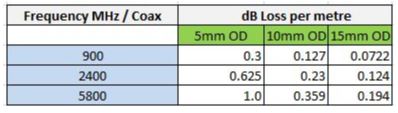
Well, yes but no. The thicker coax (15mm) does have much fewer losses (or much less attenuation) but the extra thickness means that it is less flexible and so harder to work with. Most installers don’t want to put 15mm coax into vehicles or space restricted applications. 5mm is the easiest to work with so is popular for vehicles, 10mm is suitable for many commercial applications and the losses can be largely compensated for by the gain in the chosen antenna.
There are length limits for each size coax depending on the frequency you are using. Using the right size coax for your application is critical to the success of the radio coverage/link. Please call Control Synergy and we will guide you in the available options.
CACTUS Technologies
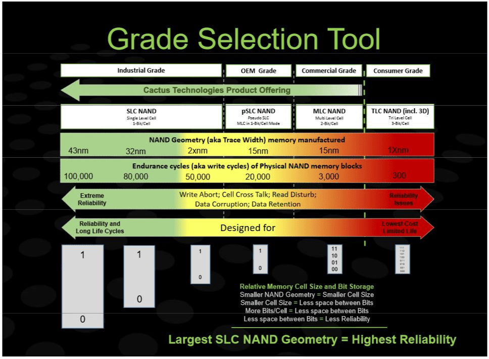
The most reliable form of NAND Flash storage is SLC (Single Level Cell) and larger geometry SLC NAND Flash storage is more reliable than smaller geometry SLC NAND Flash.
The largest geometry SLC NAND Flash available for purchase today is 43nm. This NAND Flash is spec’d at 100,000 Write cycles. Typically, this NAND is only available in legacy products, because many modern controllers are not compatible with 43nm NAND. The largest geometry NAND generally available in modern products is 34nm. By the careful use of wear-levelling, NAND friendly software and error correction, products built with 34nm SLC NAND Flash will last for many years in the field.
The bits written to a NAND Flash cell are written through the application of voltages to the individual cells. The larger geometry cells have the widest gap between voltage states which means that it is unlikely for ‘1’s to be written as ‘0’s and vice versa. The other major benefit is that SLC flash only has one bit written per cell with each cell separated from its neighbour by a reasonably thick cell wall. This means that it is much less likely for voltages to leak from one cell to another and flip the bit in that cell. As cell geometry decreases, the distance between neighbouring cells also decreases and the likelihood of voltage leaks increases. This effect is compounded when multiple bits are stored in each cell as is the case with MLC (Multi level cell) and TLC (three level cell). NAND Flash endurance reduces significantly as NAND Flash density increases. Read the CACTUS TECHNOLOGIES whitepaper on SLC v MLC NAND and the impacts of Technology Scaling.
SLC NAND is limited in supply and consequently more expensive to produce and purchase. Pseudo SLC NAND (pSLC also known as aMLC for ‘Advanced MLC’) is a technology that uses MLC NAND programmed to behave as SLC NAND in order to obtain some endurance benefits. In terms of long-term endurance, you may expect products constructed from pSLC or aMLC to have endurance somewhere between pure SLC and pure MLC. A lot will depend upon the geometry of the underlying MLC. For example, a pSLC product constructed on 24nm MLC should have a longer endurance than another product constructed from 15nm MLC. Always check with your NAND Flash supplier to confirm what geometry is being used to construct their NAND Flash Devices. For more information see CACTUS Technologies whitepaper on Pseudo SLC NAND : An Overview of Pseudo-SLC NAND
Yes. There are proprietary Self-Monitoring and Reporting Tools (S.M.A.R.T) available from most Industrial NAND Flash suppliers. Contact Control Synergy to discuss.
Yes. Cactus Technologies have produced a whitepaper which runs through the calculations you need to make to obtain a reliable estimation of NAND Flash endurance in your particular application. See the whitepaper Endurance models for CACTUS Technologies.
Control Synergy and Cactus Technologies are both focussed on the Industrial markets where the Product Life cycles need to be extremely long. Cactus technologies have the longest Product Life Cycle in the NAND Flash Industry and guarantee a Fixed Bill of Materials (BOM) for all of their official part numbers. Cactus will not change components until these components physically cannot be sourced any longer. End of Life and Product Change announcements are extremely rare and are usually issued with at least 6 months notice. We understand that once you find the correct NAND Flash part for your application, you do not want to be forced by your supplier to conduct re-qualifications and re-certifications. One way to obtain even more certainty around supply is to set up a custom part number with Control Synergy and Cactus. This will ensure that your configuration and BOM will be locked down in all future product shipments.
Yes, and this can be a very good way to ensure consistent ordering across your organisation especially for long-term projects.
Usually not, unless there is reasonably extensive Engineering involved. (For example, changing the firmware of the controller on your custom part.) Call Control Synergy to discuss.
The major problem with unexpected power outages or disturbances in the field occurs when the power event occurs during a write operation. CACTUS provide a Hardware solution built into many of their controllers, along with a Firmware solution in the form of a patented algorithm which guarantees that the last known good write can be recovered after a power event, and then write operations can be recommence from that point once suitable power conditions have been restored.
READ disturb errors have surfaced in NAND Flash products as the geometries of MLC NAND have shrunk down below 20nm. CACTUS implement 2 pieces of technology into selected products to overcome READ Disturb events and these are explained in their whitepaper.
Yes. Products come in two standard temperature ranges, 0-70 deg Celsius and -40 to 85 deg Celsius. There is also the capacity to screen for wider Operating Temperatures beyond this range if your application demands it.
Any industry that requires long term deployment of embedded systems where reliability and endurance are the major design considerations.
CACTUS Customers can be found in applications such as:
- Telecommunications
- Environmental monitoring
- Agriculture
- Defence
- Gaming
- Mining
- Mobile Computing
- Datalogging
- Point of Sale
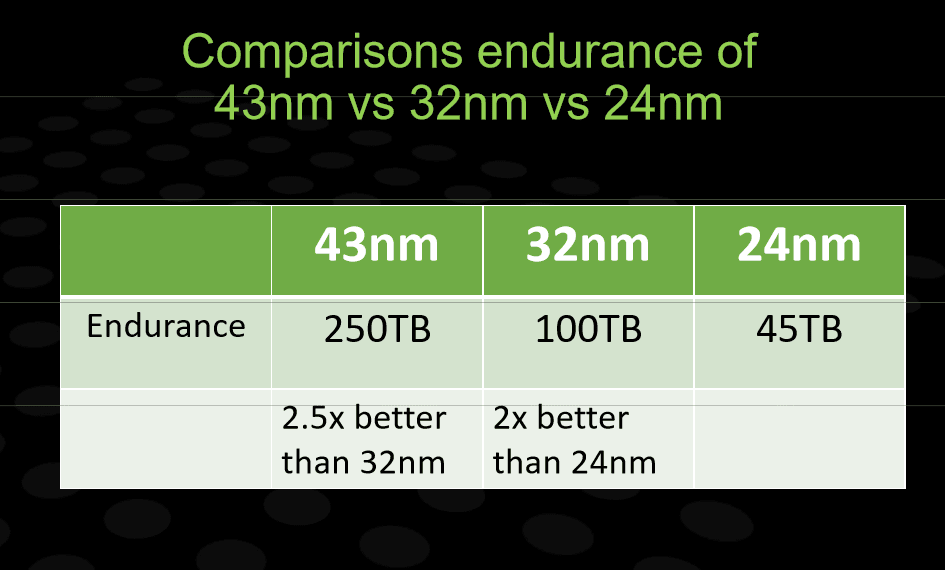
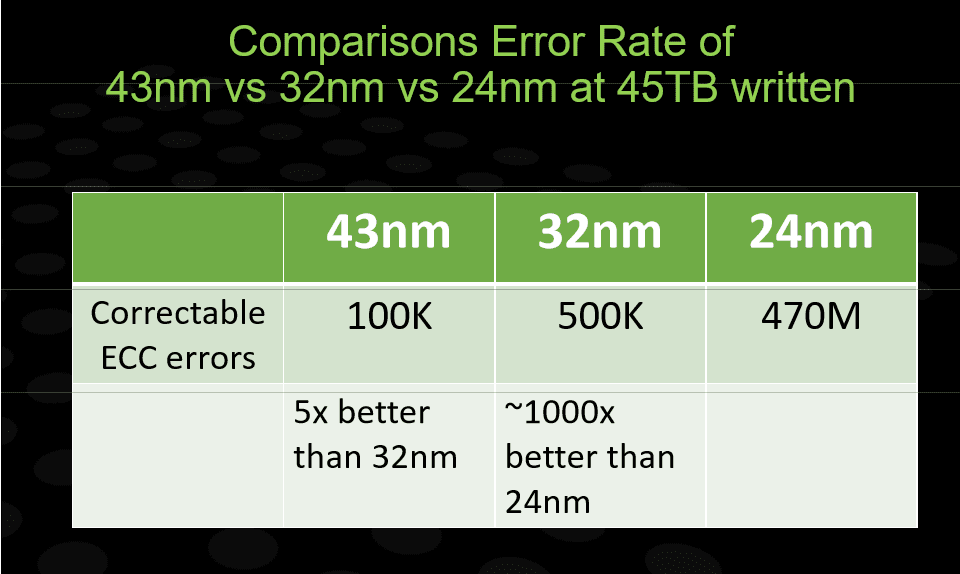
The Error rate is largely determined by the geometry of the NAND Flash used in the Product. The table below summarizes the fact that the larger geometry NAND Flash has exponentially fewer errors per TB written than the smaller geometry products:
This may be caused by the following:
- Your CF/PCMCIA to ATA adapter does not support DMA. For CF/PCMCIA to ATA adapters to support DMA correctly, the signals DMARQ and DMACK# must be connected from the connector to the ATA interface. Please check with the manufacturer of your CF/PCMCIA ATA adapter.
- Your BIOS or Firmware does not support Multiword DMA correctly. Please contact your system vendor for updated BIOS/firmware that supports multiword DMA. If the BIOS/firmware has the option to disable DMA. Disabling DMA is an interim measure, however performance may be slower without DMA. For older systems that have trouble operating with DMA enabled, CACTUS can provide non-DMA products for these systems. Their part numbers end in 2×2/2/4 to indicate standard PIO and DMA transfer modes.
- There may also be a timing issue between the product and the host ATA bus – Sometimes adding a delay for detection may help.
- Make sure that the product is running under TRUEIDE mode. TRUEID mode provides the highest performance with advanced PIO and DMA data transfer modes.
- Make sure that you use a good quality CF USB adaptor or a USB multi-card reader compliant to USB 2.0. Some USB 2.0 adaptors limit the transfer speed for both read and write operations.
- For PC Card flash cards and CF cards with CF/PCMCIA adaptors, the maximum speed is limited by PCMCIA ATA specifications to 1200-1500 kB/s. Advanced data transfer modes are not supported under PCMCIA ATA modes.
Multiword DMA (MWDMA) alleviates processor lading by directly transferring data between the disk and the memory. Data is transferred between the device and ATA bus in multiple 16-bit words. CACTUS Technologies support MWDMA mode 0, 1 and 2 by default.
- Make sure DMA mode is enabled under the BIOS. Some BIOS do not automatically enable DMA support and this may prevent Windows from using the fastest transfer mode to access the drive.
- Force Windows to re-detect the fastest DMA setting for each device on the ATA. Windows will fall back to PIO mode when 6 consecutive DMA CRC errors are encountered from the device. The only way to reset the fastest DMA mode is to remove the device from Windows, remove the device and then re-install.
- Make sure the ATA cables are in good condition. We do not recommend using 2.5” adaptor boards or long ATA cables for 2.5” SSD and DOM. Poor quality adaptor boards or ATA cables introduce noise between the drive and the host ATA bus and causes read/write errors. CACTUS strongly recommends the use of 80 pin ATA cables no longer than18 inches to be used for systems with DMA operations with PCMCIA ATA adaptors. We also recommend plugging 2.5” SSD and DOM to the host system connector directly without additional cabling. To take advantage of WWDMA support on CACTUS products, the host must support DMA in compliance to ATA specifications. CACTUS PC Cards and 203 series CF Cards must also run in TrueIDE mode to enable DMA transfer modes. CACTUS 303 series CF Cards support DMA operations in PC Card Modes also.
- Try to reformat the card with a CF/PCMCIA ATA adaptor under TrueIDE mode. Sometimes the file system can be corrupted if the file system on the CF/PCMCIA card is still mounted by the Operating System when the card is physically removed. FAT is particular susceptible to this type of corruption.
- If the cad is no longer recognised by the system under BIOS or other ATA device enumeration mechanisms then the card may require a factory low-level format as the internal device data structures may be damaged by the accidental removal.
- For product repair and warranty support please contact Control Synergy to discuss.
For PC Cards and CF Cards with CF/PCMCIA adaptors, the maximum speed is limited by PCMCIA-ATA specifications to 1200-1500 KB/s. Advanced transfer modes are not available under PCMCIA-ATA mode.
Some older Windows OS require a CF or PCMCIA to be detected as a Fixed Disk. This is a Windows feature and not related to CACTUS Technologies Products. Please talk to Control Synergy to order a CACTUS product that is detected as a Fixed part. The 2.5” SSD products are always reported to the system as a Fixed Disk.
Downloads
Below are the PDFs and documents relating to CATUS Technologies.
- An Overview of Pseudo-SLC NAND
- Endurance Models for Cactus Technologies Industrial-Grade Flash Storage Products
- Read-Disturb-Handling-of-Cactus-Tech-Flash-Storage-Devices
- SLC vs MLC NAND and The Impact of Technology Scaling
- Write Abort Handling Cactus Technologies Industrial-Grade Flash Storage Products